PCS® Insights

Sharing Industry Knowledge, Lessons-Learned and Published Presentations

Pipeline Stress 101

Engineering for Non-Engineers

The world is in constant motion. Every day we rely on infrastructure to keep us safe as we accomplish our goals. In using this infrastructure, we are subjecting it to many stresses which it must be designed to handle. If you do not notice the pipelines around you, they are operating well. The gas stove will cook your food. The heat will kick on during winter. You can fill your tank at the gas station.

Pipelines are an extremely safe way to transport energy across the country. A barrel of crude oil or petroleum product shipped by pipeline reaches its destination safely more than 99.999% of the time. The reliability of this infrastructure is assured by careful design that takes many factors of its use and environment into account. Pipelines must be designed to withstand many stresses while safely transporting hydrocarbons for many years. A single failure at any point in the pipeline will shut a large section of the system and markets down, possibly causing serious safety concerns and economic consequences to operators and the general consumer. So what exactly are these stresses that a pipeline needs to be designed to withstand? PCS Engineering gives a glimpse into pipe stress, one of the many factors that go into designing a pipeline.

1. Internal Pressure from Compressed Fluids

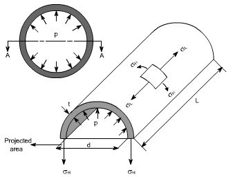
The pipeline must contain the product flowing through it. No leaks. Inside, everything is at a very high pressure and wants to escape, pushing against the edge of the pipe walls. The pipe walls need to be strong enough to withstand that force and keep that pressure directed towards making the product flow through the line.

Hoop Stress is caused by internal pressure of product flowing through a pipe
 

First, a proper pipe material must be chosen (e.g. one of many grades of steel). It must be strong enough to withstand the pressures. It also must not chemically react with the product being carried. Next the walls of the pipe must be thick enough (wall thickness, or “t” in the diagram above) to withstand the forces pushing against them. These forces are calculated based on the product flowing through the line (e.g. crude oil, natural gas, etc.) and the temperature and pressure range for which the pipeline is being designed. Another name for this internal pressure is Hoop Stress.

2. Thermal Expansion from Temperature Changes

Pipelines, like all materials, will encounter changes in temperature that cause them to expand or contract. When ten miles of steel pipe are welded together, they can grow to be 158 feet longer between a cool night and hot day (assuming a 30°F difference in temperature). This expansion only causes stress if the material is fixed at both ends. This is less of a problem when the pipe is buried, versus being above ground, as temperature swings become smaller each day and seasonally.


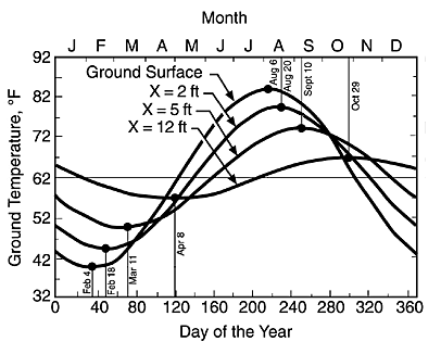
Average changes in temperature over the year. Max and min vary based on depth-of-cover. (Source)

The real change in temperature, and thus material stress, happens as soon as hot product flows through the line. The pipeline will expand to be larger than it was when it was built (about 5.27 feet per mile per 10°F change). Because the finished pipeline is fixed at both ends, this will put the pipe in-between under compression. When above-ground piping encounters cold weather or hot product stops flowing through the line, the pipe will do the opposite and contract, potentially causing tension within the materials.
 

Compression (left) and Tension (right) stresses cause different problems for a pipeline
 
Tension will cause the walls of the pipe to become thinner, and they must not become too thin to withstand Hoop Stress. Enough compression may cause the pipeline to buckle.


Pipe buckled from compression


Temperature changes are unavoidable, so how do we minimize the effects of this tension and compression?
The main strategy is to spread stresses out over as much length of the pipeline as possible, so stress is not concentrated (localized) in one area. In general, most expansion will be absorbed over longer distances by various bends in the pipeline underground that already occur with changes in direction or to follow natural land contours. In some cases, a loop is designed into the pipeline to provide more flexibility in the line and spread the stress from thermal expansion over the whole loop. See an exaggerated example below.

Loops help accommodate thermal expansion.


For above ground pipe, supports are used to restrain the pipe’s movement in multiple directions and take on some of the stress that would otherwise be borne by bends and/or tees. Supports also ensure sections of pipe do not expand into foreign territory that may contain rocks or other unexpected objects.
 

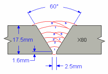
3. Material Irregularities are Sitting Targets

The forces in and around pipelines are always looking for places to release and will attack the weakest point. For a well-designed pipeline, all these forces will cause the product inside to move along the pipeline. Flaws in the design may expose weak points, but also flaws in the materials used can cause unexpected weak points. If a material has an irregularity, such as a crack or an air pocket, the force will concentrate on that area (localized force) causing it to experience higher stress. If the stress is high enough, the integrity of the whole pipeline is at stake. So even if the design is sound, we must be sure that all materials used in construction are to the design specification and do not contain irregularities.


Welds (metal that connects the pipes) are always at-risk for material irregularities as each is made individually and it is difficult to not introduce air pockets when welding. Welders are trained specifically to be as consistent as possible, but their work still needs rigorous testing. Welds are especially sensitive to tension, because any gap or irregularity in the weld or its material strength may cause localized stresses on the weld material.

Example of a weld executed in multiple passes. (Source)


Construction teams need to be certain the welding process uses a metal as strong, or stronger, than the pipe it is connecting. This process is defined and enforced by a welding specification for each combination of wall thickness, grade, and pipe diameter of the materials being welded together.


As an added precaution, every weld is thoroughly tested for defects using a non-destructive (NDE) testing process. X-Rays are sent through the weld material to make sure they are to standard thickness and have no gaps (e.g. air pockets from inconsistent weld passes).
 

Example of porosity (air pockets) in a bad weld. (Source)
 

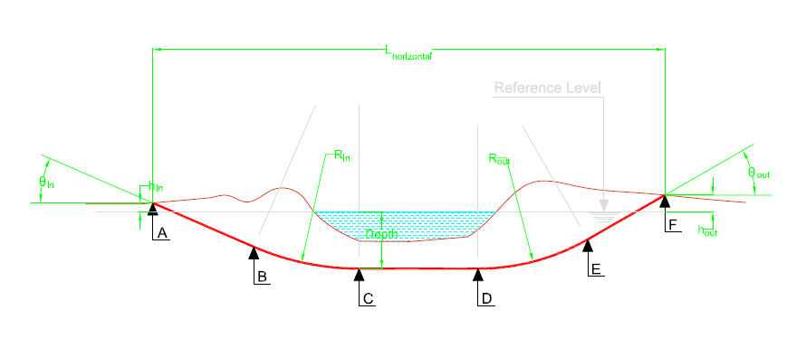
4. Heavy Loads – Soil, Trains, Buildings, etc.
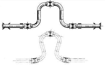
If you put something heavy and concentrated enough on top of the pipe, it will deform. Engineers need to make sure that the pipe does not carry too high of a weight or vibration. Pipe is often buried far enough underground so that the ground absorbs and/or distributes much of the forces from activity above ground. If a pipeline is going under a road, it will be deeper and have a larger wall thickness. It will get even deeper and thicker if going under an interstate, train tracks, building, etc. At the same time, the pipe needs to be strong enough to support itself and all the soil on top of it as it goes deeper in the earth.

A horizontal directional drill (HDD) profile showing a pipeline bending underneath a river. (Source)
 
Unique environmental factors also need to be taken into account. Above-ground pipelines, for example, need to be designed to withstand external wind forces. Pipelines in a marsh may need weights added around them so they do not float around. All pipelines need to account for any earthquakes or other seismic activity that may occur in the area.
 

5. Bending Stress

Wherever there is a fitting, a pipe bend, or any change in direction in the pipeline, the materials will experience a bending stress. Bending stress is a combination of compression and tension.

Bending Stress – tension on one side, compression on the other
 
Pipelines are never completely straight lines. To handle necessary changes in direction, the design will use elbows (forged fittings used to quickly change direction), segmentable ells (curved forged fittings that can be cut to a specific angle), or field bends (straight pipe that is bent in the field). Field bends are the least expensive option in the design, so are used most often. However, field bends must maintain a specified minimum bend radius to avoid buckling or thinning out the wall thickness of the pipe. If the pipeline must make a sharp turn (e.g. in a populated area or highly contoured land) that cannot be accomplished at the maximum allowable field bend radius, then a forged piece like an elbow would be used.


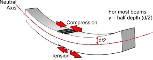
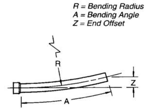
Example of a pipe bend. Each type of pipe has a maximum allowable bending radius (R in diagram) (Source)


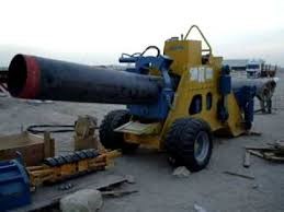
Example of a Bending machine for Field Bends

When doing a horizontal directional drill (HDD), the pipe gradually curves far underground underneath an obstacle and then gradually back up. As HDDs are long buried sections of pipe that must be pulled through the ground, elbows or field bends cannot be used to accomplish this curve.
 
Instead, these are engineered so that the natural flexibility of the pipe can be utilized to clear the obstacle.
 
For HDDs, the pipe itself deforms without any field bends or elbows
 
Initial pipeline design is done with simplified engineering calculations that exist for hoop stress, road crossings, HDD profiles, minimum wall thickness and choosing appropriate materials for all of the scenarios a section of pipeline may encounter. For more detailed stress analysis after the initial design, software like Ceasar is used. Software can take many more factors into account to validate that the pipeline design is sound.
 
Software is used for detailed stress analysis (Source)


Additionally, standards pertaining to the specifications used to design piping that takes these stresses into account are in place to help the industry to design, build, and operate pipelines safely. These standards are also checked and updated yearly based on any new information available or common practices proven in the field.


After the pipeline is constructed, it must be tested for weak points before it can be put into service. Pressurized water is put into the pipeline and held at a pressure much higher than it will encounter under normal operations. This is called a hydrotest and is used to check for leaks or possible weak points in the line. Having accounted for the many stresses a pipeline may experience in its design and performing rigorous testing, we can be very confident the pipeline will be up for the job for years to come.


Article Details

Author: Zackery Breeland

Engineer
PCS® Metairie

More Information

Contact Us

We would appreciate any opportunity to assist you, and to connect you with the right person at PCS ® to address your needs and answer any questions.

Request Info Call Us  1-800-643-8306